
In the IoT field, where several devices communicate and exchange data, a lightweight and efficient messaging protocol is necessary to ensure reliable and scalable communication. MQTT (Message Queuing Telemetry Transport) is a protocol that fits this requirement well and has become a de facto standard for IoT deployments.
This tutorial will show how easy and fast you can prototype your next IoT project by combining the efficiency of MQTT with the well-known Arduino platform.
What is Arduino?
Arduino is an excellent open-source electronics platform that has gained immense popularity among hobbyists and tech enthusiasts. Arduino’s greatest strength lies in its versatility, featuring a variety of microcontrollers - which are small, programmable devices that allow you to interact with the physical world by reading sensor inputs and controlling outputs. Atmel microcontrollers typically power these boards and come equipped with built-in input/output pins, analog and digital interfaces, and many other features.
Arduino is an absolute choice for anyone passionate about electronics and eager to bring creative projects to life. Its user-friendly interface and extensive catalog of ready-to-use libraries allow even beginners to grasp the basics of programming and electronics quickly.
In this article, I will utilize the Arduino Uno WiFi Rev2 (Figure 1), which is widely considered the most straightforward entry point to IoT within the Arduino board family.
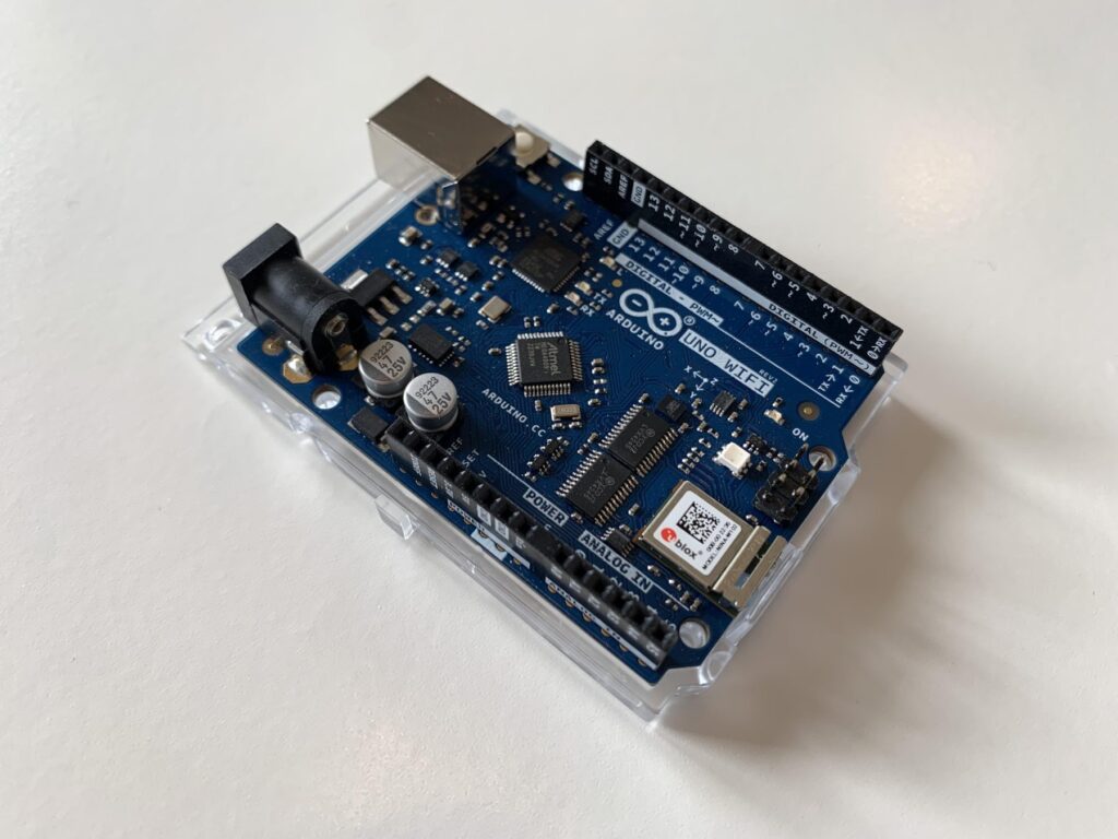
Figure 1 - The Arduino Uno WiFi Rev2 board used in this project.
This specific version has the following main characteristics:
| Microcontroller | ATmega4809 |
|---|---|
| Digital I/O Pins | 14 — 5 Provide PWM Output |
| PWM Digital I/O Pins | 5 |
| Analog Input Pins | 6 |
| Flash Memory | 48 KB (ATmega4809) |
| SRAM | 6,144 Bytes (ATmega4809) |
| EEPROM | 256 Bytes (ATmega4809) |
| Clock Speed | 16 MHz |
Table 1 - Main characteristics of an Arduino Uno WiFi Rev2 board.
Visit the official Arduino website for further details on the Uno WiFi Rev2 board.
Arduino and MQTT: An example of a perfect match!
Despite Arduino’s strengths, its main constraints lie in its limited resources, particularly in terms of memory. Arduino boards typically have limited RAM and flash memory capacities, which can pose constraints when working on complex projects with extensive code or data storage requirements, and it’s here where the MQTT protocol plays a key role.
MQTT is an excellent fit for small resource devices due to its lightweight protocol design. With minimal overhead and efficient data transmission, MQTT optimizes memory and bandwidth usage, making it ideal for constrained environments like Arduino. This enables small devices to communicate seamlessly and reliably while conserving valuable system resources for other applications.
Designing the Arduino MQTT project
Before diving into the practical aspect of my Arduino MQTT project example, let’s take a moment to describe the design implementation. In my setup, the Arduino board will act as a publishing client, while the subscriber and the broker will be deployed on a Windows PC using the Mosquitto MQTT broker. Figure 2 shows a graphical representation of the project design.
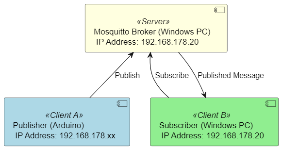
Figure 2 - Design of my MQTT project example.
The Mosquitto MQTT broker remote access option must be enabled for this configuration. Arduino will periodically publish a message containing a simulated temperature reading, demonstrating the implementation of MQTT over Arduino.
Before proceeding with the Arduino MQTT publish implementation example, explore the Cedalo MQTT Platform to elevate your solution with the Pro Edition for Eclipse Mosquitto™ broker. Sign up for a free Cedalo MQTT Platform trial for access to advanced broker features such as MQTT High Availability, enhanced security, management APIs, or a high-performance local persistence database.
Let’s get started: Install and configure the Arduino IDE
If you just purchased your Arduino and have no prior experience on this topic, it is also highly probable that you still need to install the IDE on your PC. If you already have the IDE installed, skip to the “Install board package and libraries” section below.
Let’s begin by downloading the latest Arduino IDE.
I will select the Windows version for this tutorial, but versions for Linux are also available. Once the download is complete, open the executable to start the installation.
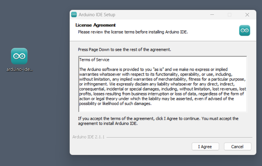
Figure 3 - Click on the installer to start the installation.
Wait for the setup to complete, then open the IDE, and the following window will appear:
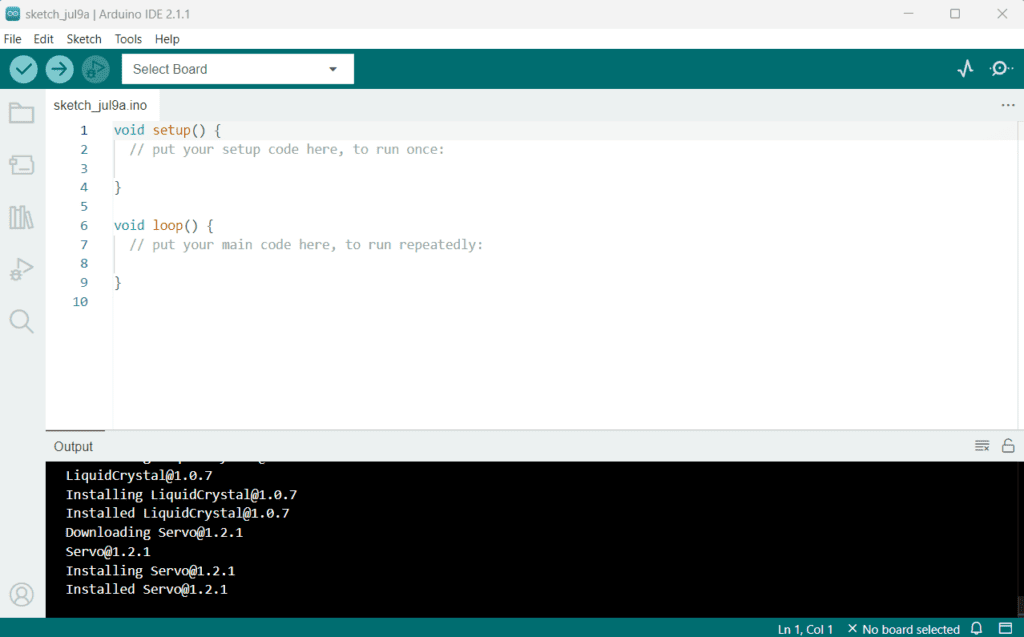
Figure 4 - Arduino IDE window.
When starting the Arduino IDE for the first time, it will update some libraries and install some drivers. The drivers are necessary to connect and program the Arduino boards properly.
Installing the Arduino board package and libraries
It is necessary to install the appropriate software packages and libraries for the Arduino board I will use for the example, which are:
- Board specific libraries
- Libraries for Wifi connection
- MQTT library
To do this, go to Tools > Board > Board Manager in the IDE menu bar, look for the Arduino megaAVR Boards package, then click Install (Figure 5). This package enables the Arduino UNO WiFi Rev2 board to be supported. Please note that the package name may differ if you have a different board.

Figure 5 - Install the correct board package.
After installing the support package for the board, I can proceed with installing the necessary software libraries, which are ArduinoMqttClient for managing MQTT and WiFiNINA for WiFi support.
Simply need to navigate to Tools > Manage libraries to install the two libraries.
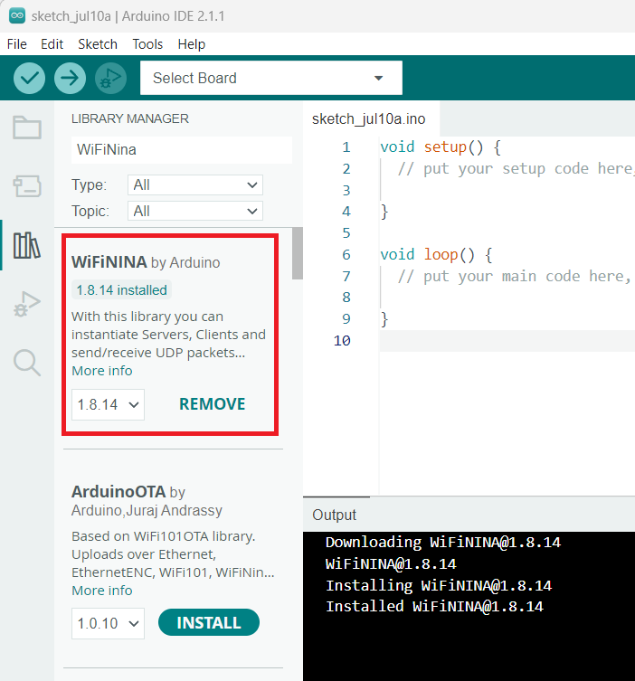
Figure 6 - Install the software libraries.
With the configuration of the IDE now complete, I can proceed with writing the software.
Writing the Arduino software
I will program my Arduino board to publish periodic messages on the MQTT topic /home/room/temperature. The message will contain a temperature value simulating an actual measure made by a home automation system, and will be sent within a cyclical period of 5 seconds.
The flowcharts in Figures 7 and 8 depict the software idea divided into two parts: the initialization and the actual software functionality. The “setup” function represents the initialization, while the “loop” function describes the software functionality. It is important to note that the Arduino IDE creates a setup and loop function by default, and I will write all the software inside these functions.
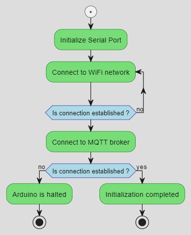
Figure 7 - Flowchart depiction of the initialization routine (represented by the setup function that runs once on startup).
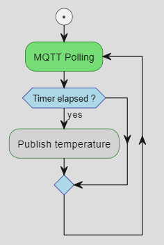
Figure 8 - A flowchart depiction of the functionality routine described as the loop function. Also called repeatedly.
Now, lets copy and paste the following code snippet into the project. The language used in this example is C++, often used to program Arduino, in combination with C.
#include <WiFiNINA.h>
#include <ArduinoMqttClient.h>

char ssid[] = "SSID";       // Replace with WiFi SSID
char pass[] = "PASSWORD";    // Replace with WiFi Password

WiFiClient wifiHdlr;
MqttClient mqttClient(wifiHdlr);

const char brokerAddr[] = "192.168.178.20";     // Use the real broker ip address
const char topic[] = "/home/room/temperature";

const long intTimer = 5000;               // Timer interval for publishing the message
int currentTemp = 25;                     // Simulated temperature value in °C
unsigned long prevTimer = 0;              // Variable used to keep track of the previous timer value
unsigned long actualTimer = 0;            // Variable used to keep track of the current timer value

void setup()
{
  //Initialize serial port with standard speed of 9600 bps
  Serial.begin(9600);

  // Connect to WiFi network
  Serial.print(": Connecting to WPA SSID: ");
  Serial.println(ssid);
  while (WiFi.begin(ssid, pass) != WL_CONNECTED) {
    // Connection not established, retry
    Serial.println(": Retry");
    delay(3000);
  }

  Serial.println(": Connection established");
  Serial.println();

  Serial.print(": Connecting to MQTT broker: ");
  Serial.println(brokerAddr);

  // Connect to MQTT broker
  if (!mqttClient.connect(brokerAddr, 1883)) {
    Serial.print(": MQTT connection failed! Error code = ");
    Serial.println(mqttClient.connectError());
    // The connection to the MQTT broker failed, Arduino is halted.
    while (1);
  }

  Serial.println(": Connection established");
  Serial.println();
}

void loop()
{
  // call poll() regularly to handle keep alive and library
  mqttClient.poll();

  actualTimer = millis();

  // Check if the timer is expired
  if (actualTimer - prevTimer >= intTimer) {
    // save the last timestamp a message was sent
    prevTimer = actualTimer;

    // Post some debugging information on serial port
    Serial.print(": Sending message to topic: ");
    Serial.println(topic);
    Serial.println(currentTemp);

    // Publish message
    mqttClient.beginMessage(topic);
    mqttClient.print(currentTemp);
    mqttClient.endMessage();

    Serial.println();
  }
}
Setting up the software structure
As mentioned, the software structure relies on two functions: setup and loop, which the Arduino software structure defines by default. The setup function is where I will initialize my system and all that I need later in the program (e.g., peripherals, libraries). This function only executes once after a power cycle of the board.
For my project, the setup function starts the serial port and WiFi module, ensuring the device is connected and running. The initialization routine is the best choice since all these steps must be executed only once.
After completing the initialization function implementation, I can proceed with the actual program functionality. The loop function is where I can place my actual program, which Arduino executes it cyclically - making it the right place for the program body.
The program is fairly straightforward. First, start by polling the MQTT handler using the poll() method of the mqttClient object. This step is necessary for handling the library’s keep-alive timer and internal states. Once this is complete, I can check the current timer status. When the timer elapses, Arduino will publish the current temperature value using the methods beginMessage(), print(), and endMessage(). I will simulate the temperature value to be 25 °C. As an added feature, Arduino will log the complete process on the serial port for debugging purposes.
Start the test: Arduino and MQTT in action
Now Arduino is ready to run and publish the message. But first, I must ensure that the correct environment is set up, as demonstrated in Figure 2.
Let’s start the broker on the Windows PC by typing the following command into a Powershell console:
.\mosquitto.exe -v -c .\mosquitto.confThe configuration file must contain the correct settings to enable the Remote Access functionality. This is necessary to allow “remote” connections, like those originating from my Arduino client.
An earlier tutorial on Raspberry Pi explains how to activate remote access on the Mosquitto MQTT broker. But, if you require personalized support that meets your specific needs, consider exploring the professional technical support options.
To start the subscriber, input the following command into a second Powershell console:
.\mosquitto_sub -h localhost -t /home/room/temperatureThe broker and subscriber are now ready, and I can start my Arduino client.
Connect the Arduino board to the PC through the USB connection, and select it through the Arduino IDE, as shown in step 1 from Figure 9.
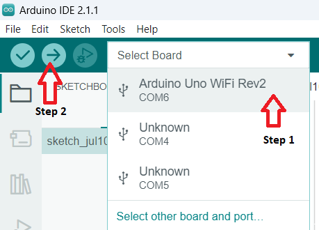
Figure 9 - Select the board to program.
Then click on the arrow (as shown in step 2) to compile the program.
If no issues are present in the source code, the program will start and the compilation output console will show the ROM and RAM usage information.
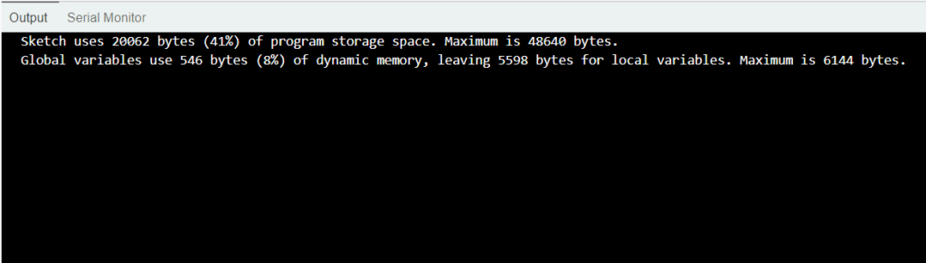
Figure 10 - Output of the compilation process.
To view the logged output of Arduino, simply switch to the serial monitor view by clicking on Tools > Serial Monitor (Figure 11). The serial monitor window will appear (Figure 12), and I’ll be able to see all the relevant output.
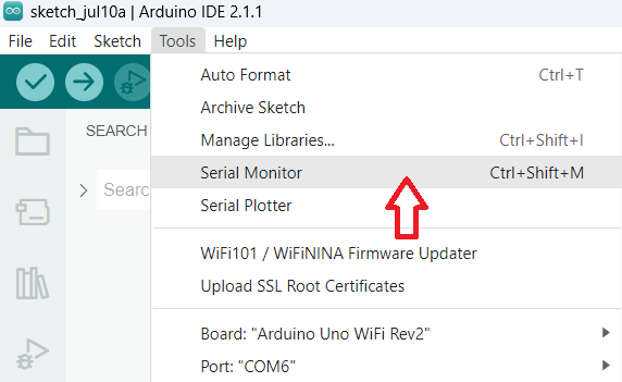
Figure 11 - Open the serial monitor.
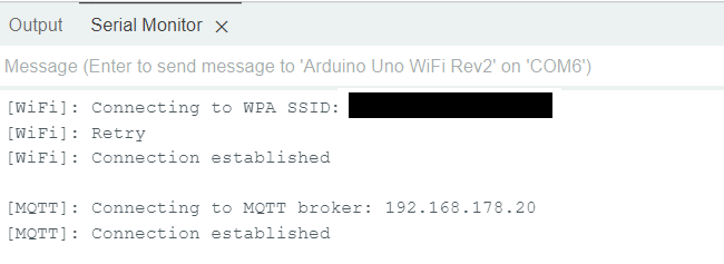
Figure 12 - Log from Arduino to the serial monitor.
As you can see from Figure 12, Arduino will try to connect to the WiFi network and then to the MQTT broker.
After establishing the connection with the MQTT broker, the Arduino client will cyclically publish the simulated temperature value every 5 seconds. As shown in the subscriber console (Figure 13), the temperature numerical value of 25 °C reaches the subscriber.
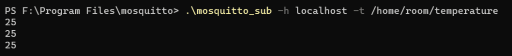
Figure 13 - The subscriber receives the published temperature.
Conclusions
In this project, I successfully integrated MQTT with Arduino, demonstrating the synergy between these two technologies in the world of IoT.
MQTT’s lightweight, publish-subscribe messaging protocol has proven to be an ideal fit for Arduino, enabling smooth communication between devices. The configuration process was straightforward, accentuating Arduino’s user-friendly nature.
A significant advantage of working with Arduino was the availability of pre-written libraries. These libraries saved valuable development time, allowing me to focus on the implementation of the desired functionalities.
In conclusion, combining MQTT and Arduino offers a practical and efficient solution for IoT projects.


